
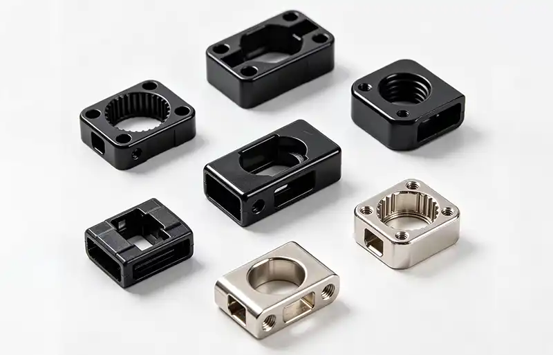
Injection-molded plastic parts are the default answer for almost any polymer component that has to be strong, dimensionally repeatable, and produced in quantity. The process is mature and forgiving — but only for parts designed with it in mind. The difference between a part that tool up cleanly on the first shot and one that needs three rounds of cavity rework is almost always a design decision made before anyone touched steel.
How the process actually works
Molten thermoplastic is injected into a steel cavity under pressure, held until it solidifies, then ejected. The injection molding cycle repeats every 15 to 120 seconds, depending on part size, wall thickness and material.
What matters for a designer is the order of events inside the mould:
- Fill — melt travels from the sprue through the runner and into the cavity. Where two flow fronts meet, a weld line forms.
- Pack and hold — pressure is maintained to feed material into the shrinking part. This is the stage that controls final dimensions and how much sink marking appears.
- Cool — the part solidifies. Cooling typically accounts for 50 to 70% of the cycle, and cooling time scales with the square of wall thickness. A 4 mm wall takes roughly four times as long to cool as a 2 mm wall.
- Eject — the part is pushed off the core, then trimmed and finished.
Two consequences follow directly. First, a part with a uniform wall thickness cools predictably, while one with a thick section next to a thin one will cool unevenly and distort. Second, because cooling dominates the injection molding cycle, the fastest way to reduce cycle time is to reduce wall thickness, not to run a faster machine.
Shrinkage: the number that governs every dimension
Every plastic shrinks as it cools, and the amount is large enough to change your drawing. The single most useful fact in moulding is that shrinkage depends on the material’s molecular structure.
Amorphous polymers — ABS, polycarbonate, PS, PMMA, rigid PVC — have randomly arranged chains that softens gradually as they cool. They shrink 0.2 to 0.8%, and they do so evenly in every direction.
Semi-crystalline polymers — PP, nylon, POM, PBT, PET — pack their molecules into ordered crystalline regions as they cool. Those regions pack tighter than the amorphous structure, so they shrink 0.8 to 3.5% and shrink more in one direction than another.
| Material | Shrinkage (%) | Structure |
| ABS | 0.4 – 0.7 | Amorphous |
| Polycarbonate (PC) | 0.5 – 0.8 | Amorphous |
| PMMA (acrylic) | 0.2 – 0.8 | Amorphous |
| Polypropylene (PP) | 1.0 – 2.5 | Semi-crystalline |
| Nylon PA6 / PA66 | 0.8 – 1.5 | Semi-crystalline |
| POM (acetal) | 1.8 – 2.5 | Semi-crystalline |
| PET | 1.2 – 2.0 | Semi-crystalline |
| HDPE | 1.5 – 3.5 | Semi-crystalline |
Glass-filled grades break the single-number model. Fibres resist shrinkage along their own length, so a filled part shrinks less in the flow direction than across it. PA66-GF30 might shrink 0.3–0.5% along flow and 0.7–1.0% across it. That asymmetry is the classic cause of warped filled parts: a flat panel that shrinks 0.4% one way and 0.9% the other cannot stay flat. For any filled resin with tight flatness or concentricity requirements, flow-direction and cross-flow shrinkage have to be requested separately.
Design rules that prevent most problems
Draft angle. Every vertical face on an injection molded part needs taper so it releases instead of dragging. 0.5° covers most situations, 2° minimum where shut-off is required, and 3° or more for textured surfaces, where deep texture increases the effective draft needed.
Wall thickness. Keep it uniform, and keep it within what the material handles well:
| Material | Recommended wall thickness (mm) |
| ABS | 1.14 – 3.56 |
| Polycarbonate | 1.02 – 3.81 |
| Polypropylene | 0.89 – 3.81 |
| Nylon | 0.76 – 2.92 |
| Acetal (POM) | 0.76 – 3.05 |
| Polyphenylene sulfide | 0.51 – 4.57 |
Ribs. Use ribs to stiffen a panel rather than thickening it, at roughly 50–60% of the nominal wall thickness. A rib at full wall thickness is simply a thick section with all the shrinkage problems that implies, and it will sink.
Bosses for fastener holes should be about the same thickness as the wall they sit on, with a fillet at the base where they meet it.
Undercuts are possible but need side actions or lifters in the tool, which raise both cost and lead time. Avoiding them keeps the mould simpler.
Radii on corners reduce stress concentration and reduce the risk of cracking during moulding. Sharp internal corners are a common cause of failure.
Common defects and their root causes
| Defect | Root cause | Correction |
| Short shot | Insufficient injection pressure or speed, mould too cold, poor gate design | Raise melt temperature or injection speed, increase hold pressure, move or enlarge the gate |
| Flash | Clamping force too low, worn mould clearance, excessive pressure | Increase clamping force, check mould fit, correct pressure settings |
| Sink marks | Thick section or rib root, insufficient packing | Even out wall thickness, reduce rib thickness, increase hold pressure and time |
| Weld lines | Two flow fronts meeting, poor venting | Improve venting, increase injection speed, raise mould temperature, reposition the gate |
| Warpage | Uneven cooling, residual stress, uneven shrinkage | Balance cooling channels, uniform wall thickness, control fibre orientation |
| Burn marks | Trapped air compressing and igniting | Clean or deepen vents, reduce injection speed |
| Silver streaks | Moisture in the resin | Dry the material properly before processing |
Injection molding defects are not random. Each one traces back to a specific process parameter or geometry decision, which means most are designed out rather than adjusted out.
Tolerances and finish
General-purpose injection-molded parts typically hold to about ±0.1 mm, with tighter figures achievable on critical features and dependent on geometry, material and shrinkage control. The honest limit is set by shrinkage variability, not by machining capability — the cavity is cut to a scaled dimension, so if the resin’s shrinkage is not known precisely, the part cannot be.
Surface finish is set by the cavity itself. A polished steel tool produces a gloss finish; a textured tool produces a textured part. SPI finish standards run from SPI-B1 at roughly 2–3 Ra up to SPI-A2 at 1–2 Ra. For cosmetic parts, this is a tooling decision made once and lived with for the life of the tool.
Common questions
What is the minimum wall thickness for injection molding? Around 0.5–0.8 mm depending on material, with 1 mm a safer general choice for structural parts.
How much does an injection-molded part shrink? 0.2–0.8% for amorphous resins and 0.8–3.5% for semi-crystalline ones. The exact value should come from the resin grade’s data sheet, validated against a first-shot sample.
Can injection molded parts have tight tolerances? General parts hold around ±0.1 mm. Tighter tolerances on specific features are achievable, but they require validated shrinkage data and, in critical cases, a secondary machining operation.
Are undercuts possible on injection molded parts? Yes, using side actions or lifters, but they add tooling cost and lead time. Designing them out is usually cheaper.
Do fibre-filled parts warp more? They can, because glass fibres align with the melt flow and make shrinkage directional. This is a design and gate-placement issue rather than a material defect.
Injection molding rewards parts that were designed for the process. A part with uniform walls, adequate draft, correctly scaled dimensions and ribs rather than thickened sections will tool up and run cleanly — and the design rules that achieve this are not difficult, only easy to overlook.