
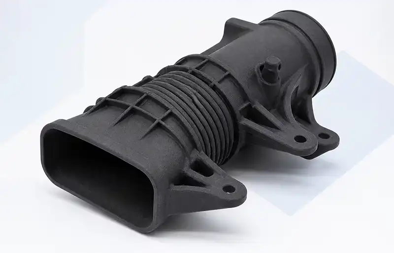
MJF 3D printing — Multi Jet Fusion — is the powder bed technology that sits closest to injection moulding in material behaviour, while skipping the tooling entirely. It is the process behind most of the functional nylon parts now replacing machined prototypes and short-run moulded components. Here is how MJF 3D printing actually works, where it beats SLS, and the design rules that decide whether a part comes out right.
What Multi Jet Fusion actually is
MJF was developed by HP and released commercially in 2016. It belongs to the powder bed fusion family, sharing its basic principle with SLS — a bed of plastic powder is built up layer by layer, and loose powder supports the part above, so no support structures are needed. What MJF changed is how the powder is fused.
Instead of a laser tracing each cross-section point by point, MJF uses an inkjet printhead to deposit liquid agents onto the powder, then passes infrared energy across the entire build area at once. The consequence is straightforward: no laser, much faster throughput, and parts with consistent properties in every direction. That combination is what separates MJF 3D printing from other powder bed options.
The five stages of the MJF process
1. Powder spreading. A recoater spreads a thin layer of nylon powder across the build platform, typically 80 microns thick, held just below its melting point.
2. Fusing agent application. The inkjet head jets millions of droplets of a black, infrared-absorbing fusing agent onto the powder bed, tracing the cross-section of each part in that layer to roughly 21-micron accuracy.
3. Detailing agent application. A second agent is deposited around the edges of each part. It inhibits fusion there, keeping loose powder as a barrier that produces clean boundaries and sharp edges.
4. Energy exposure. An infrared lamp sweeps across the bed. Where the fusing agent sits, the powder absorbs the heat and melts into a solid cross-section; the surrounding powder stays loose. Because the entire layer is heated at once, layer time is predictable regardless of how many parts are in the build.
5. Layer repetition, cooling and depowdering. The platform drops, fresh powder is spread, and the cycle repeats. After the build the chamber cools, parts are removed from the powder cake, excess powder is cleared by compressed air and bead blasting, and unfused powder is recovered for reuse.
MJF vs SLS: where the difference shows
Both technologies print nylon parts with no support structures, so the comparison is worth doing properly.
| Factor | MJF | SLS |
| Fusion method | Inkjet agents plus infrared energy | CO2 laser, point-by-point |
| Throughput | Fuses a full layer at once | Slower on large batches |
| Mechanical properties | Consistent in all directions | Varies with build orientation |
| Surface finish | Smoother, more consistent | Rougher, more variation |
| Colours | Natural grey, dyeable | White and natural, wider range |
The speed advantage of MJF 3D printing scales with batch size. On a single part the difference is not dramatic; on a build of fifty or more components, fusing whole layers rather than tracing them makes MJF the cheaper and faster option per part.
Isotropy is the quieter advantage. Because the whole layer is heated together rather than a laser moving along a contour, the thermal history is more uniform and mechanical properties stay consistent regardless of orientation. For a load-bearing component, that predictability matters more than speed.
Materials available
PA 12 nylon is the workhorse, with tensile strength around 48 MPa, elongation at break around 20%, and heat deflection temperature up to roughly 175 °C. It is chemically resistant and tough.
PA 11 offers higher impact resistance and better heat performance than PA 12, at a higher material cost. PA 12 with glass bead adds stiffness and dimensional stability, suiting jigs and dimensionally critical brackets. TPU provides a flexible elastomer for grips and seals, and polypropylene is available for chemical resistance or living hinges.
Design guidelines that decide whether it works
- Minimum wall thickness of 0.8 mm, with 1.0 mm recommended for reliable fusion.
- Minimum hole diameter of 1.5 mm, pin diameter of 1.0 mm, and minimum feature size of 0.5 mm.
- Escape holes of 3.5 mm or larger diameter in any enclosed cavity, so trapped powder can be removed.
- 0.5 mm clearance between moving features printed as an assembly.
- Consistent wall thickness. Thick sections cool slower and can warp; very thin walls may not fully fuse. Sections above roughly 5 mm carry more deformation risk.
- Build volume on the most widely deployed machines is around 380 × 284 × 380 mm.
Parts come out in a characteristic grey, because the fusing agent is black and dispersed through the material. Dyeing is the usual route when appearance matters — painting directly onto a printed surface bonds poorly.
Where MJF fits against other processes
MJF 3D printing is strongest for functional prototypes and low-volume end-use parts in batches of roughly 20 to 500 pieces, particularly where geometry is complex, internal channels matter, or the part has to be strong enough to test.
Against SLA, MJF wins on strength and batch economics and loses on surface finish. Against FDM, it wins on detail, isotropy and speed. Against injection moulding, it wins when volume is too low to justify a steel tool.
The most common mistake is treating MJF as a material substitute for a moulded part. A nylon MJF part is not a production ABS part, and a test that depends on production material behaviour should be run on a moulded or machined part instead.
Common questions about MJF 3D printing
Does MJF need support structures? No. Loose unfused powder supports the part during printing, so no additional support geometry is required.
Can MJF parts be used in production? For low and mid-volume production, yes — this is one of the main reasons the technology exists. For high volume, injection moulding remains more economical.
What is the tolerance on MJF parts? Roughly ±0.3 mm, or ±0.3% depending on feature size, with an 80-micron layer thickness.
Can MJF parts be dyed? Yes, dyeing is standard. Painting directly onto a printed surface bonds poorly, so specify the colour before printing.
MJF is one of several powder bed technologies available for functional prototyping and low-volume production, alongside SLS, SLA, SLM and conventional CNC machining. The right choice comes down to batch size, geometry, material requirements and how much the part has to behave like a production component.